Use this document to choose values that are both manufacturable and meet your needs.
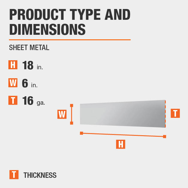
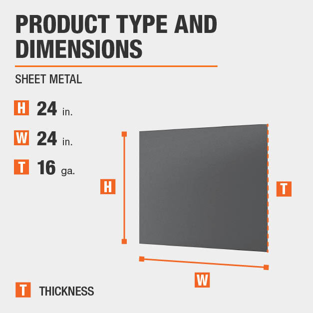
Bend relief size for 16 gauge sheet metal.
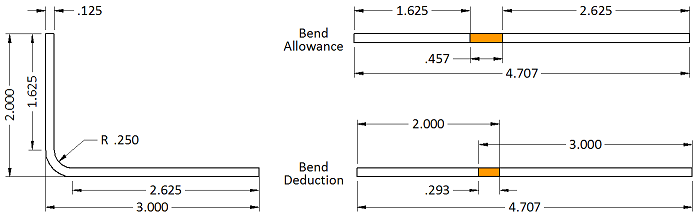
The minimum bend radius data shown in these charts is measured to the inside of the bend.
A bend relief creates space between the bent and unbent surfaces so that the edge of the sheet metal is perpendicular to the bend itself.
To eliminate this a bend relief is added so the edge of the sheet metal is perpendicular to the bend.
One benefit of a bend relief is that it makes the part easier to produce.
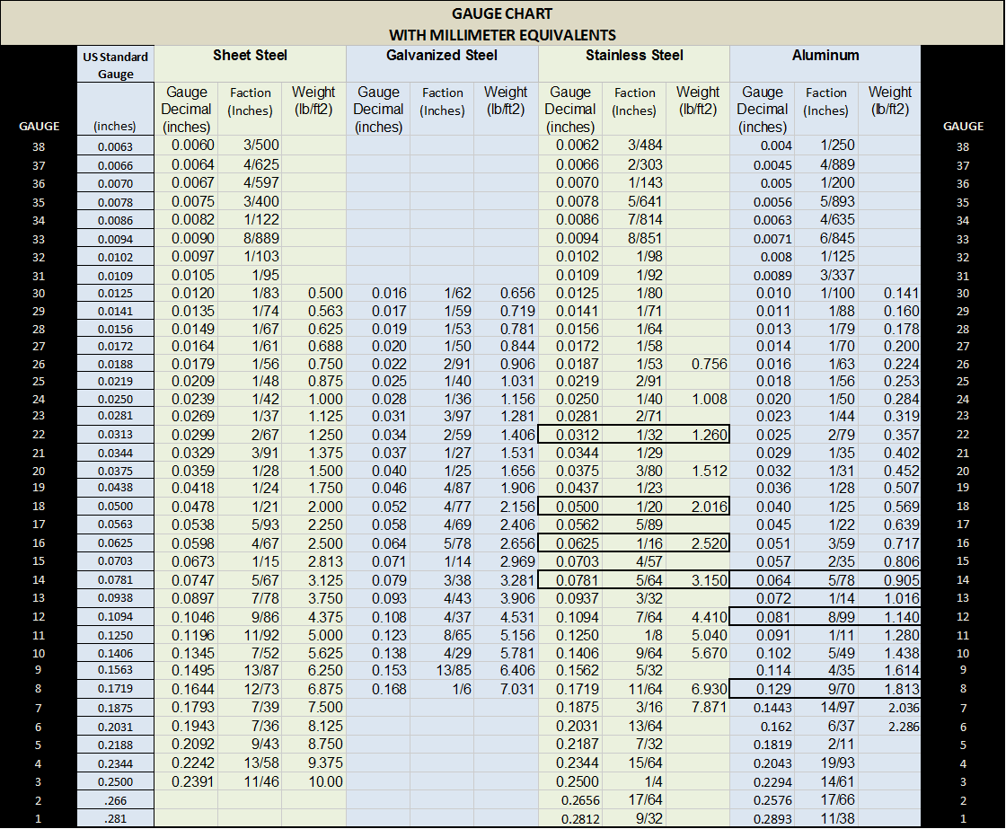
When designing sheet metal parts and enclosures it is helpful to use these values as the basis for your design.
When the sheet metal is put through the process of bending the metal around the bend is deformed and stretched.
The gap between the bend and surrounding material allows us to shape the sheet in the press brake cleanly eliminating cracking and tearing.
The bend radii listed are standard minimum if manufacturing for aircraft and aerospace applications.
Bend radii minimum bend sizes.
For example if you make a partial flange as above using all the defaults the software makes relief cuts at the end of the bends as shown to the right.
Since commercial sheet metal bending can be done with less concern for stresses caused during forming operation the radius can be near zero for thin sheet metal.
As this happens you gain a small amount of total length in your part.
The bend allowance and bend deduction are two measures that relate the bent length of a piece of sheet metal to the flat length.
If it is ok for the metal to rip the minimum bend relief is zero.
When the sheet metal is put through the process of bending the metal around the bend is deformed and stretched.
A 1 degree tolerance on all bend angles.
Bend radii minimum bend sizes it is most economical to use a single bend radius throughout the design but if necessary you can utilize multiple radii.
Likewise when you are trying to develop a flat pattern you will have to make a deduction from your desired part size to get the correct flat size.
Sheet metal parts with a minimum of 0 9mm to 20mm in thickness can be manufactured.
Likewise when you are trying to develop a flat pattern you will have to make a deduction from your desired part size to get the correct flat size.
Synchronous sheet metal is pretty cool even cooler than just normal synchronous modeling if you ll excuse that word.
In general a minimum bend relief is equal to the material thickness plus the inside bend radius.
Therefore the bend allowance added to the flange lengths is equal to the total flat.
Bend radii and minimum bends are limited to certain values or ranges which are determined by the equipment and tooling combinations available to the manufacturer.
As this happens you gain a small amount of total length in your part.